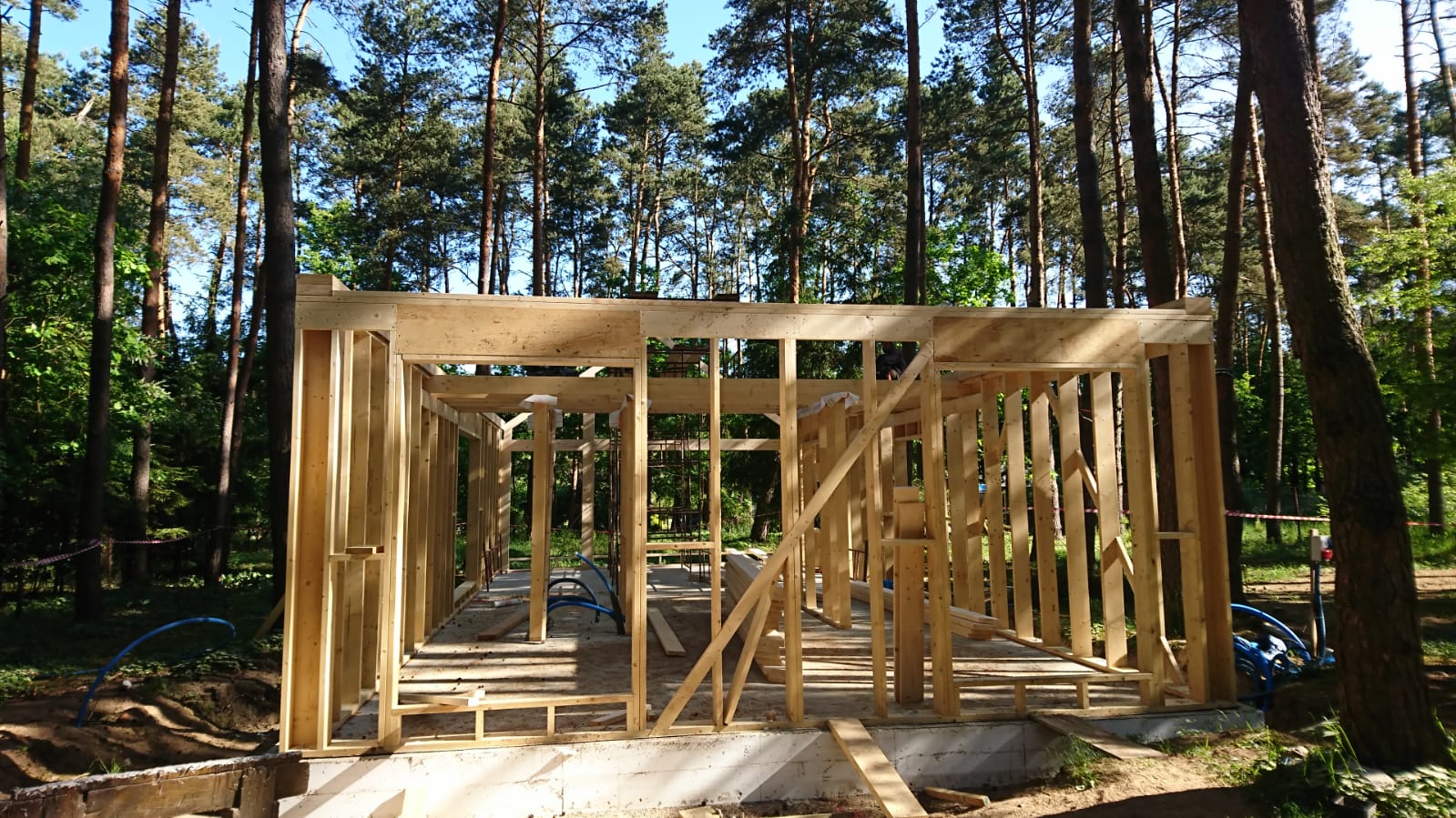
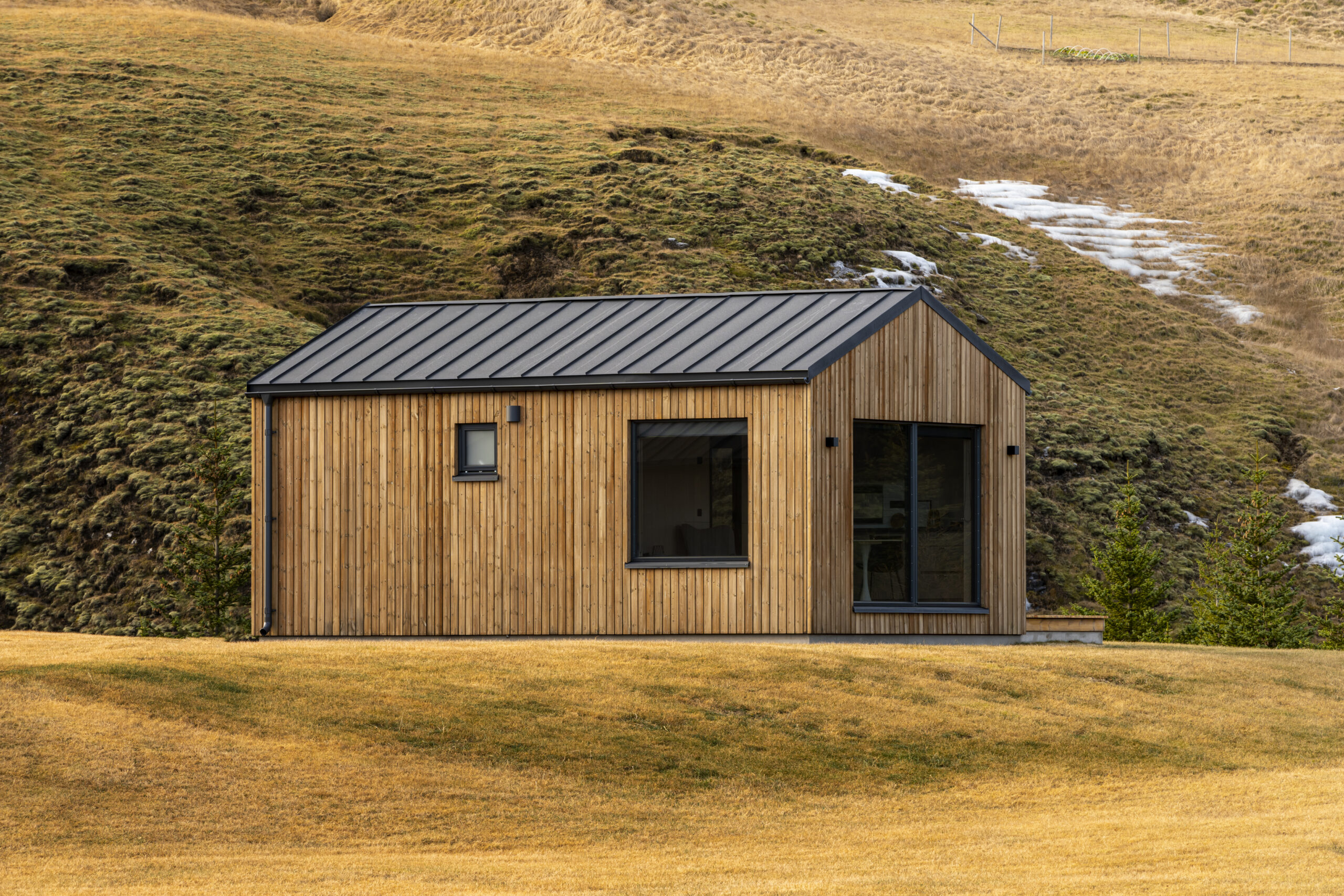
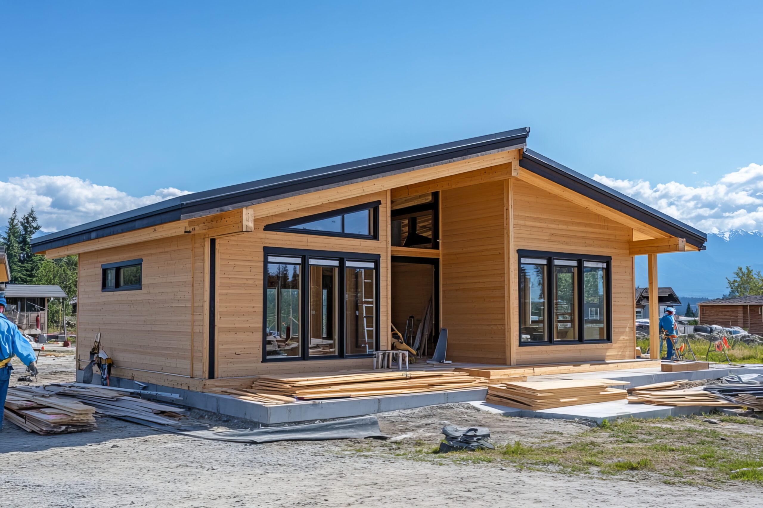
Short construction time
Construction takes much less time than with traditional building methods.


Timber houses · STEICO system
Healthy, warm and energy-efficient homes built by a family business with over 15 years of experience in Poland and Sweden.
Why Skan-Pol
Construction takes much less time than with traditional building methods.
Timber-frame construction supports environmental protection.
Timber-frame houses are energy efficient.
We have been building timber-frame houses for over 15 years.
Wood is the healthiest material for building a home.
We are a family business with traditions spanning generations.
About us
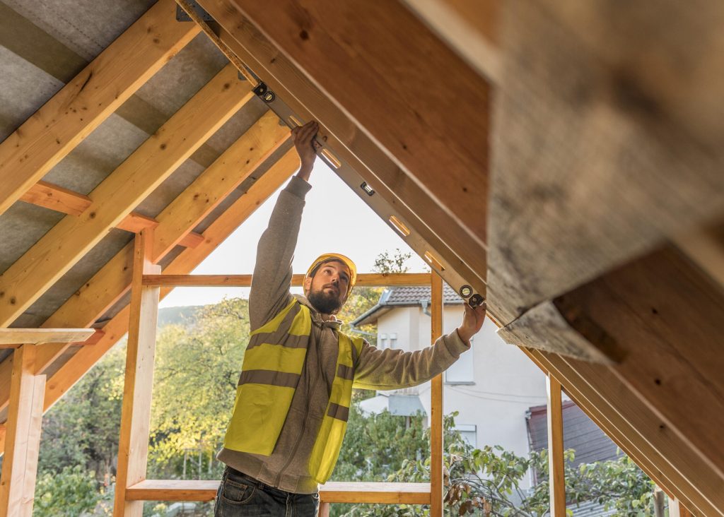
We have specialised in building timber-frame houses for over 15 years.
We gained experience in both the Swedish and Polish markets, but our love of wood goes back generations. We are a family business sharing the same values and passions. We build healthy, energy-efficient homes using the best solutions available to us.
Get to know usOur services
Construction
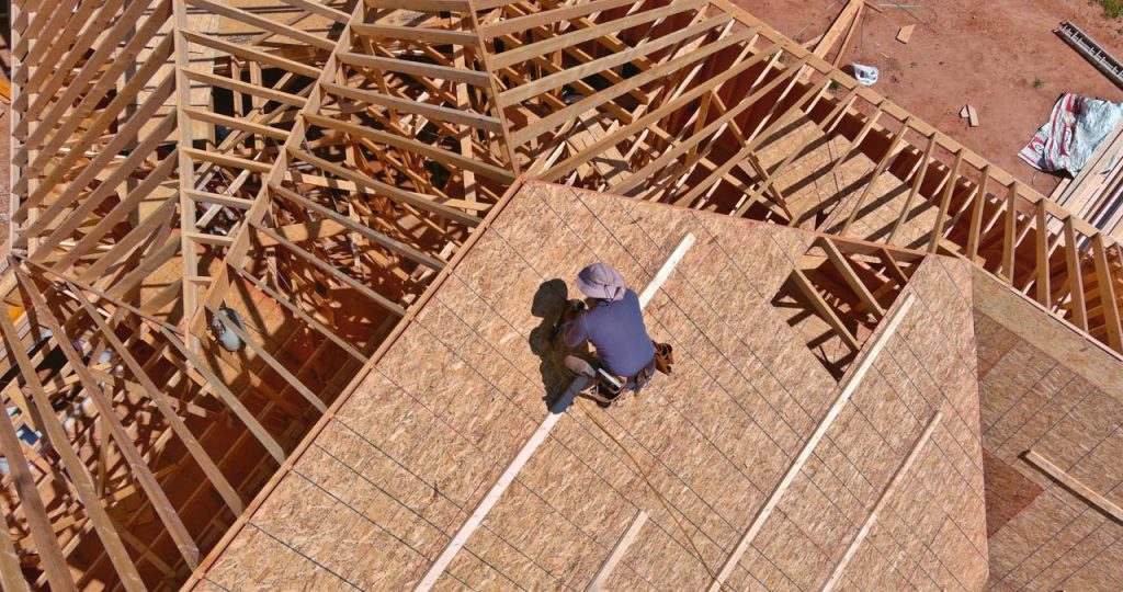
Complete delivery of an energy-efficient home using the proven STEICO system.
Explore the scope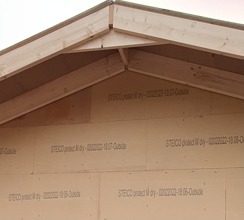
Technology
Natural materials, excellent insulation and a healthy indoor climate all year round.
Explore the systemHow we work
We learn about your needs, plot and design.
We prepare a clear scope of work and cost estimate.
We agree on the technology, materials and schedule.
We carry out the work to the agreed standard.
We check every detail and hand over your home.
Our projects


Selected Google reviews
Real experiences from clients who entrusted us with building their homes.
★★★★★
Google“Efficient and professional.”Kasia Ch5/5 review on Google
★★★★★
Google“Stands out from the competition.”Honorata Gawlas5/5 review on Google
★★★★★
Google“We are happy with the result.”Robert J5/5 review on Google
★★★★★
Google“Highly recommended.”Rafał Łuniewski5/5 review on Google
★★★★★
Google“We sincerely recommend them!”Seba Seba5/5 review on Google
★★★★★
Google“I definitely recommend this company.”Natalia Konecka5/5 review on Google
★★★★★
Google“Thoroughly professional.”Janusz O5/5 review on Google
★★★★★
Google“Everything as agreed.”Tadek Kobek5/5 review on Google
Technology explained
Select building elements and layers to explore timber-frame construction.
Preparing the 3D model…
3D is not available in this browser. You can still view the drawing and all layer descriptions.
Sub-base — medium sand mechanically compacted to Is = 0.97
Rotate with one finger and pinch with two to zoom in or out. Swipe outside the model to scroll the page.
Sub-base — medium sand mechanically compacted to Is = 0.97
Use + and − to zoom in or out. You can also rotate the model using the arrow buttons.
Details informed by photographs of one of our projects. This is an illustrative model; services are shown through the layers to make their routes clear.
The white loop shows underfloor heating in the floor screed, above the insulation and foil, not within the structural reinforced-concrete slab. Pipe spacing, thicknesses and routing are illustrative and must be specified for each project.
The services illustrate routing principles, not an installation design. Penetrations, seals and positions require individual design; the image does not indicate drilling locations in the structure.
Foundation slab

Select a number on the drawing to read the layer description.
Section 1 of 7
Selected layer 1: Sub-base — medium sand mechanically compacted to Is = 0.97
Preparing the 3D model…
3D is not available in this browser. You can still view the drawing and all layer descriptions.
System thin-coat mineral render
Rotate with one finger and pinch with two to zoom in or out. Swipe outside the model to scroll the page.
System thin-coat mineral render
Use + and − to zoom in or out. You can also rotate the model using the arrow buttons.
Details informed by photographs of one of our projects. This is an illustrative model; services are shown through the layers to make their routes clear.
The services illustrate routing principles, not an installation design. Penetrations, seals and positions require individual design; the image does not indicate drilling locations in the structure.
External wall with render

Select a number on the drawing to read the layer description.
Section 2 of 7
U = 0,12 W/(m²K)
Selected layer 1: System thin-coat mineral render
Preparing the 3D model…
3D is not available in this browser. You can still view the drawing and all layer descriptions.
Timber facade board
Rotate with one finger and pinch with two to zoom in or out. Swipe outside the model to scroll the page.
Timber facade board
Use + and − to zoom in or out. You can also rotate the model using the arrow buttons.
Details informed by photographs of one of our projects. This is an illustrative model; services are shown through the layers to make their routes clear.
The services illustrate routing principles, not an installation design. Penetrations, seals and positions require individual design; the image does not indicate drilling locations in the structure.
Wall with timber cladding

Select a number on the drawing to read the layer description.
Section 3 of 7
U = 0,12 W/(m²K)
Selected layer 1: Timber facade board
Preparing the 3D model…
3D is not available in this browser. You can still view the drawing and all layer descriptions.
Plasterboard, 12 mm
Rotate with one finger and pinch with two to zoom in or out. Swipe outside the model to scroll the page.
Plasterboard, 12 mm
Use + and − to zoom in or out. You can also rotate the model using the arrow buttons.
Details informed by photographs of one of our projects. This is an illustrative model; services are shown through the layers to make their routes clear.
The services illustrate routing principles, not an installation design. Penetrations, seals and positions require individual design; the image does not indicate drilling locations in the structure.
Internal wall

Select a number on the drawing to read the layer description.
Section 4 of 7
U = 0,38 W/(m²K)
Selected layer 1: Plasterboard, 12 mm
Preparing the 3D model…
3D is not available in this browser. You can still view the drawing and all layer descriptions.
Ceiling structure — C24 timber, 60×220 mm
Rotate with one finger and pinch with two to zoom in or out. Swipe outside the model to scroll the page.
Ceiling structure — C24 timber, 60×220 mm
Use + and − to zoom in or out. You can also rotate the model using the arrow buttons.
Details informed by photographs of one of our projects. This is an illustrative model; services are shown through the layers to make their routes clear.
The services illustrate routing principles, not an installation design. Penetrations, seals and positions require individual design; the image does not indicate drilling locations in the structure.
Ceiling below an unoccupied attic

Select a number on the drawing to read the layer description.
Section 5 of 7
U = 0,08 W/(m²K)
Selected layer 1: Ceiling structure — C24 timber, 60×220 mm
Preparing the 3D model…
3D is not available in this browser. You can still view the drawing and all layer descriptions.
Plasterboard, 12.5 mm
Rotate with one finger and pinch with two to zoom in or out. Swipe outside the model to scroll the page.
Plasterboard, 12.5 mm
Use + and − to zoom in or out. You can also rotate the model using the arrow buttons.
Details informed by photographs of one of our projects. This is an illustrative model; services are shown through the layers to make their routes clear.
The services illustrate routing principles, not an installation design. Penetrations, seals and positions require individual design; the image does not indicate drilling locations in the structure.
Intermediate floor

Select a number on the drawing to read the layer description.
Section 6 of 7
U = 0,14 W/(m²K)
Selected layer 1: Plasterboard, 12.5 mm
Preparing the 3D model…
3D is not available in this browser. You can still view the drawing and all layer descriptions.
Roof tiles or tile-profile metal roofing
Rotate with one finger and pinch with two to zoom in or out. Swipe outside the model to scroll the page.
Roof tiles or tile-profile metal roofing
Use + and − to zoom in or out. You can also rotate the model using the arrow buttons.
Details informed by photographs of one of our projects. This is an illustrative model; services are shown through the layers to make their routes clear.
This model shows the roof structure. Electrical services are shown in the wall and ceiling sections.
Roof above an unoccupied attic

Select a number on the drawing to read the layer description.
Section 7 of 7
U = 0,14 W/(m²K)
Selected layer 1: Roof tiles or tile-profile metal roofing
Guide
Let’s start with the numbers
Choose the floor area, house type, roof and garage. We will send your estimate by email.